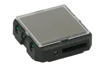
STM550B
STM 550B is a flexible self-powered multi-sensor module capable of measuring temperature, humidity, illumination, magnet contact status and acceleration. It enables the realization of energy harvesting wireless sensors for light, building or industrial control systems communicating using the 2.4 GHz Bluetooth Low Energy (BLE) communication standard.
Technical specifications
Power supply: integrated solar cell
Consumption: <1W
Radio frequency range: 2.4GHz (Bluetooth BLE advertising)
RF power max: +8dBm
Operating Temperature: -5 °C … +45 °C (indoor use in dry rooms only)
Operating Humidity: 0% to 90% r.h. (non-condensing)
Range: Up to 30m line of sight / 10m indoor environment
Temperature measurement range / accuracy: -25°C… +65°C / +-0.3K
Humidity measurement range / accuracy: 0 … 100 % r.h. / +- 3 % r.h.
Illumination measurement range / accuracy: 0 … 65000 Lux / +-10 %
Acceleration measurement range / resolution: +- 4 g / 0.002 g
Acceleration threshold for immediate report: 0.03 g (default, configurable)
Update rate (excl. random offset): Every 60 seconds (configurable)
Minimum light level for self-supplied operation 200 lux for 6 hours per day(2)
Operating time in darkness (at 25°C) 4 days (after full charge with default settings)
Backup battery type (optional) CR1632
Operation time with backup battery: Renata CR1632 (137 mAh) Infrequent bright light (200 lux for 2 hrs per day): 8 years / Consistent low light (50 lux for 6 hrs per day): 7 years / Total Darkness: 5 years
Dimensions : 40 mm (l) x 40 mm (L) x 13 mm (h)
Use cases and installation
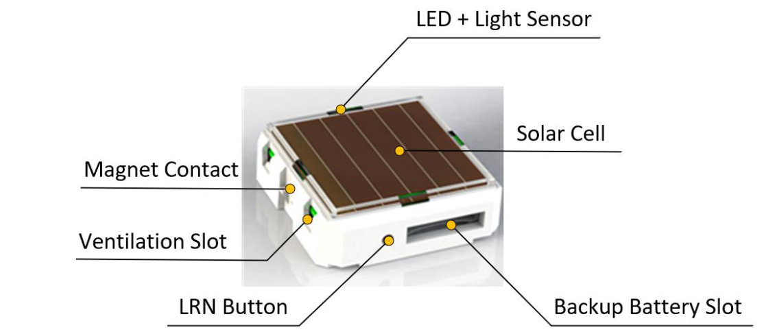
Front side
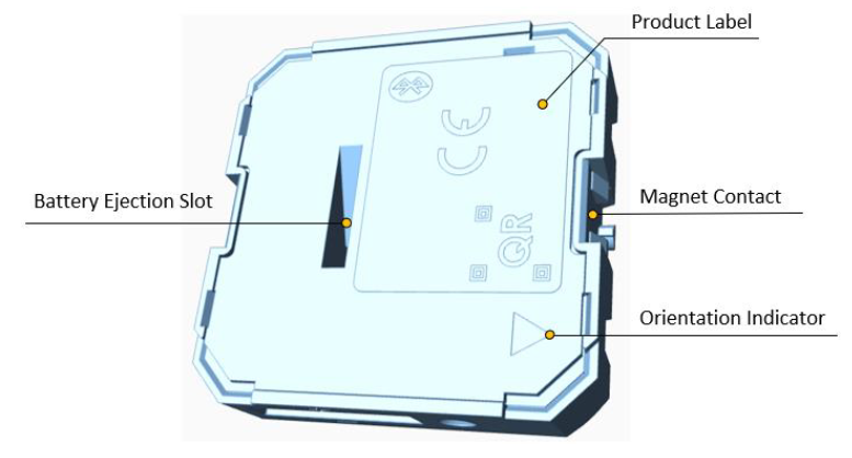
Back side
Temperature and humidity measurement
The dedicated temperature and humidity sensor integrated into STM 550B accurately measures and reports temperature and humidity present at its surface.
- Installation height
The sensor should be installed at a height that is representative for the use case. For the case of an office, the sensor should be mounted at desk level.
- Sun light or heat exposure
The sensor should be mounted such that it is not directly exposed to sunlight or heat (e.g. close to a radiator)
- Disturbances
The sensor should be mounted such that the influence from disturbances such as the air stream from air condition units is minimized. Consider also the possible tempera- ture gradient between wall and room when mounting the sensor directly onto a wall.
- Air flow
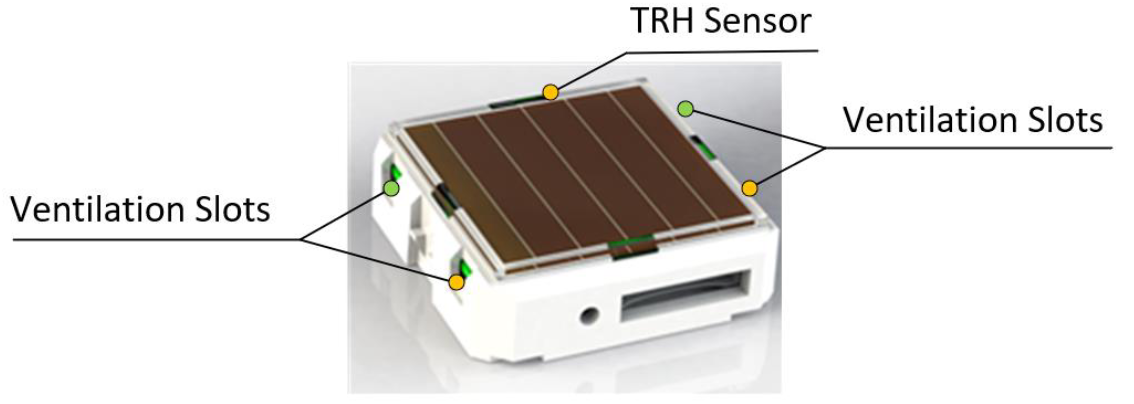
The sensor should be mounted such that the airflow from the target measurement area towards the air inlets is maximized. This will ensure the lowest possible response time of the sensor. Avoid mounting the sensor in niches or slots with little air flow.
When designing your own housing around an STM 550B module, consider the location of the ventilation slots (there are four of them in total).
Housing design has to maximize the airflow towards these slots focusing especially on the two slots nearest to the sensor which are marked with a green dot.
Acceleration sensor
Acceleration sensors measure the acceleration vector in all three dimensions {x; y; z}. This sensor can be used both to determine the device orientation (relative to the earth gravity vector) and the device acceleration (e.g. if a device is moved or shaken).
This principle can be used for two major use cases:
The approximate location of an object can be tracked based on the strength of the received periodic data telegrams. Movement of the object (e.g. from one room to another) can be detected based on the reported acceleration vector change.
The utilization of an object (a machine that is running, a chair that is occupied, …) can be tracked based on the characteristic vibrations associated with this utilization.
The following points should be considered to maximize the reliability of acceleration measurement:
STM 550 should be firmly attached to the asset without any damping to ensure that any vibration of the asset will be properly propagated to STM 550.
STM 550 should be attached to the asset at the location where the vibration is maximized. For instance, when tracking the utilization of office chairs, the highest acceleration is typically observed at the back rest.
The acceleration threshold for wake-on-acceleration should be selected such that utilization / motion is reliably detected without false triggers due to spurious vibration (e.g. people walking by)
Should the default sensitivity be insufficient even at the lowest threshold then the sampling rate should be increased
Illumination measurement
STM 550B offers the option to measure the ambient light level either via the ambient light sensor or via the solar cell.
The ambient light sensor measures and reports the light level with a spectral response close to the human eye’s perception of ambient light. The following points should be considered when using the ambient light sensor:
Aperture
The sensor measures the light level within a small radius around its centre axis. If the lighting conditions within that area are not representative for the overall conditions, then the result might be different from expectation.
Surface
The most common application for a ceiling-mounted illumination sensor is to measure the light level at a working desk surface underneath. In this application, the measured light level depends on the reflectivity of the surface. Simply put, a dark desk surface will give a totally different result compared to a white desk surface even when the same luminous flow is directed towards it.
Obstruction
Any obstruction between the sensor and the intended measurement area (desk sur- face, window) will significantly impact the measurement result. Maintaining a clear line of sight between measurement area and illuminations sensor is therefore essential.
Interference
To ensure accurate measurement results, it is essential to minimize interference from other light sources not contributing to the illumination at the target measurement area. For instance, when measuring the light level at a desk surface, interference might occur due to direct light from the window or from or upwards emission of indirect light sources (floor lamps etc)
Solar cell
The solar cell has a much larger area and aperture compared to the ambient light sensor. Therefore, the light level measured by the solar cell is typically more representative of the average illumination within a wider area.
Note that the solar cell does not apply a spectral response curve close to the human eye’s perception of ambient light to the received illumination. The illumination reported by the solar cell will therefore typically be larger than that reported by the ambient light sensor depending on the spectral properties of the ambient light.
Calibration at the receiver is suggested to obtain best results for the given lighting situation.
Magnet contact sensing
If STM 550B is used to detect the presence of a magnet using its magnet contact sensor (e.g. for door or window monitoring), then the magnet has to be in close proximity to the magnet contact sensor for the case where a “Magnet Present” (or “Closed”) condition shall be detected.
Attach the magnet to the intended surface (e.g. door or window) such that the centre of the large side of the magnet is oriented towards the location of the magnet contact sensor in STM 550B and that the distance between magnet and STM 550B housing is less than 1 cm for the “Magnet Present” condition. Verify that the state (e.g. door open or closed) is reported as expected.
Energy harvesting
STM 550B is powered by ambient light using its integrated solar cell. For best performance it is therefore essential to maximize the amount of light available for harvesting.
Harvestable light will typically be either natural light (daylight coming in through windows etc) or artificial light (direct or reflected light from indoor luminaires). If natural light is avail- able (e.g. from a window) then the solar cell of STM 550B should be oriented as much as possible towards that.
STM 550B is designed to operate self-supplied with its standard parameters based on 200 lux of illumination at its solar cell for at least 6 hours per day.
Certifications
ETSI EN 301 489-3:V2.1.1
ETSI EN 301 489-17 V.1.1
ETSI EN 300 328 V2.2.2
EN 62368-1: 2014 + A11:2017
ETSI EN 301 489-1 V2.1.1
EN 55032: 2015
EN 55035:2017
EN60669-1:1999+A1:02+A2:08
EN60669-2-1:2004+A1:09+A12:10
EN62479:2010